Assignment 4
Written on October 31st , 2022 by Petrina Chan
Assignment 4 - Milling
Files
3DM
DXF
Gerber
STL
A few notes to start off with:
This took way longer than I expected/planned it to. The final result is not exactly what I envisioned either, but it works! And I learned quite a few things that I would do differently if I had more time.
Process:
Planning
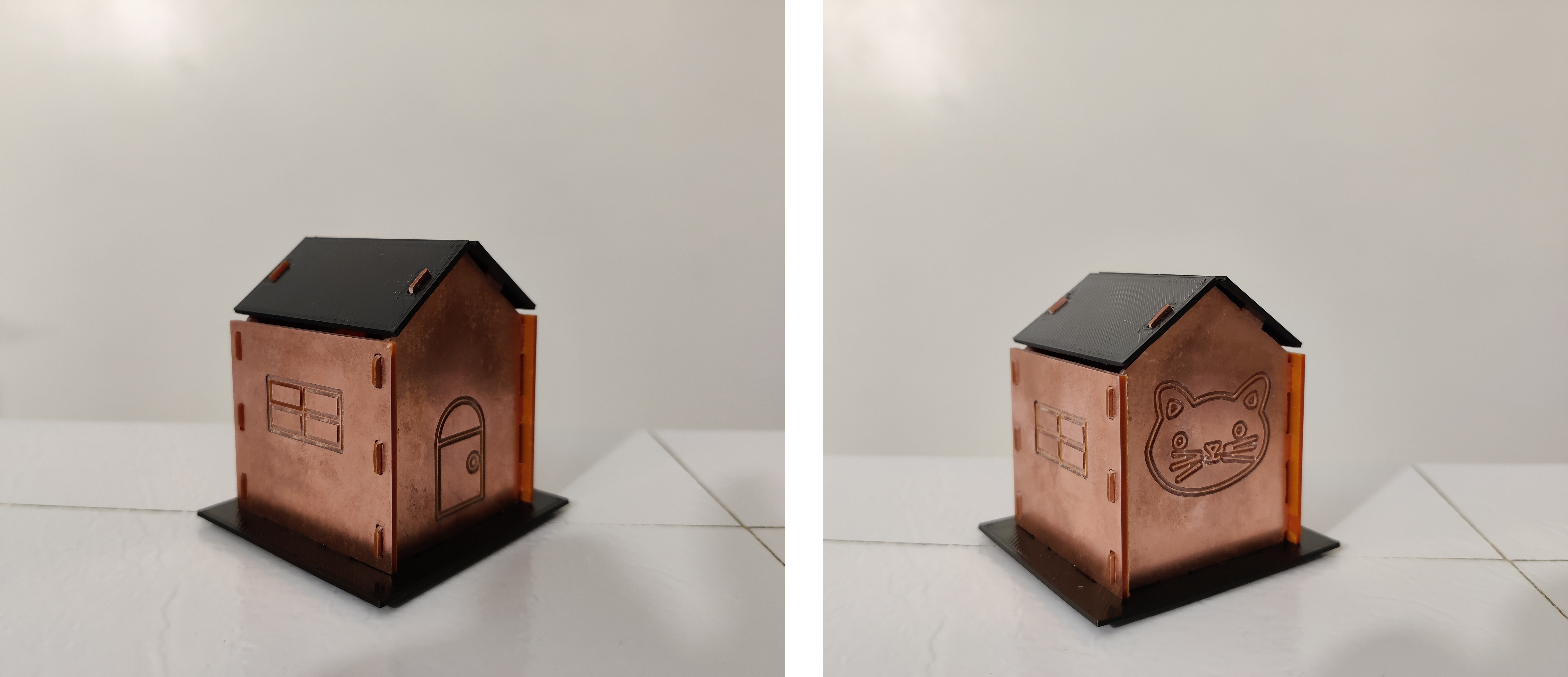
I wanted to make something a little more interesting than just a box, but I knew I couldn’t challenge myself too much both because of time constraints and my general difficulty with geometry and spatial reasoning. I thought it might be cute to do a mini house! My initial inspiration was a bird house, and I was going to make a hole in the front, but I decided to save that idea for another time and just figure out the basics first.
First I made a crude sketch of the geometry of the house and what my vision for it was, including the full house and the separate pieces that would fit together to make it. For some reason, my brain could wrap itself more around the idea of slots rather than finger joints, so I also planned where on the pieces might make sense for some tabs and slots. The “house” shaped pieces would have tabs on all sides that would fit into the corresponding holes in the side and roof pieces. In addition, both house-shaped and side pieces would have tabs on the bottom to fit inside the base piece’s holes.

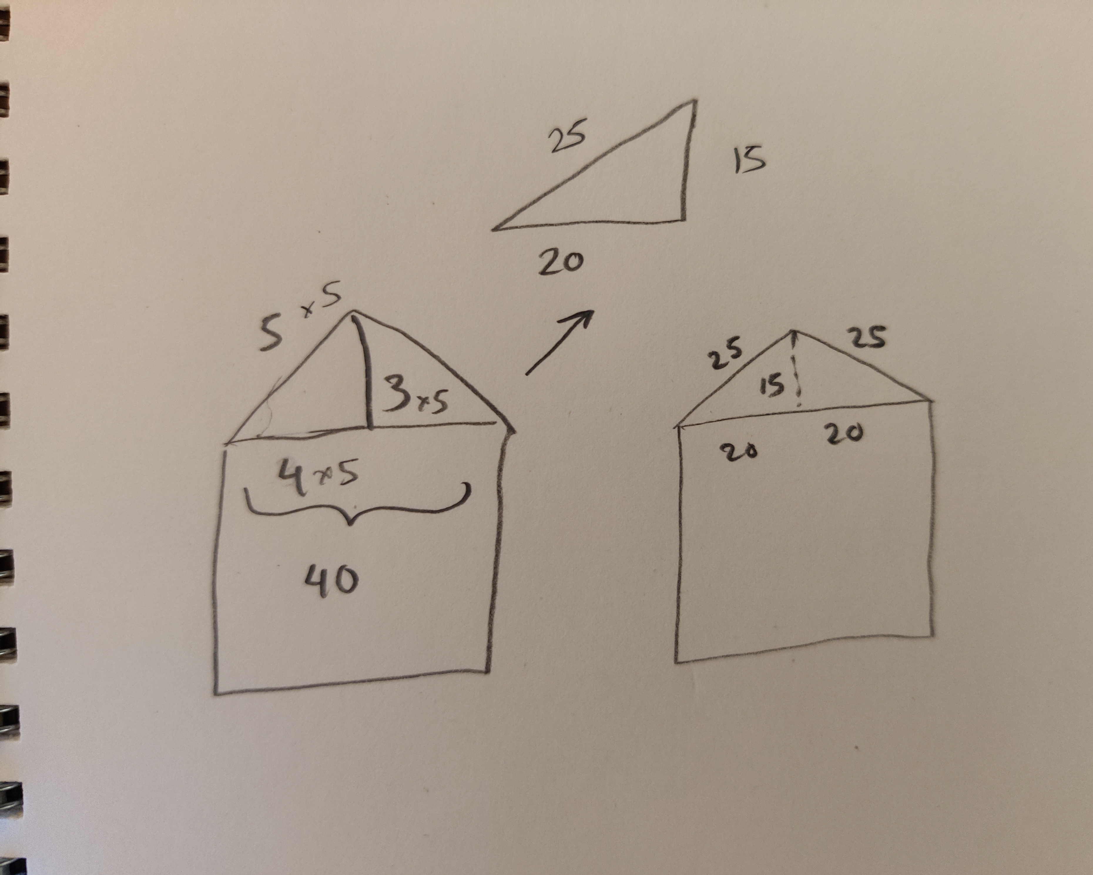
Next, I took some measurements. First, the thickness of the FR1, which was 1.4mm. Next, I approximated how large I wanted my panels to be. I based them off of a 40x40mm square. The square side panel measured 40x40mm to the holes. The main body of the house panel also measured 40x40mm (before tabs) and the dimensions of the roof part of this panel is based on a 3-4-5 right triangle (see below). Since each right triangle has a leg measurement of 20mm (40mm/2), we can use this to calculate the other leg and the hypotenuse by following the rule.
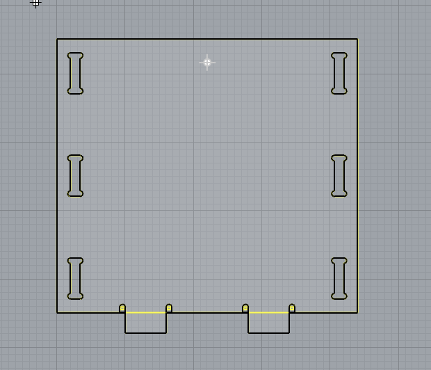
The base slots are calculated based on the distance between the tabs on the panels arranged in a 40x40mm square. The actual borders of the base panel are scaled up from there after placing the holes.
I just eyeballed what I thought would be an appropriate size of the tabs, which was 6x3mm.
The size of the holes is based on the thickness of the FR1 and tab size. Since the FR1 is 1.4mm thick, I made the holes 1.4mm wide and 6mm long since that is the size of the tabs.*
- I did not realize until later that we were supposed to scale either the tabs down or holes up to better ensure a fit when milling, thus I had to sand a fair bit to get my fit even barely working.
Making pieces in Rhino:
For the most part, my pieces were mainly simple shapes, squares, rectangles, polygons, and don’t require much explanation beyond the dimensions of the above. All tabs and slots are placed equidistant from the mid point of each side with an extra 2mm added to sides of the panels where the slots hit the edge.
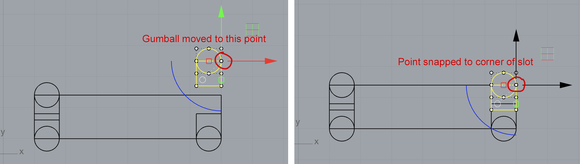
Since I was originally planning on milling all of my pieces, I made dog bones for all of my slots and tabs. To do this, I made circles with a radius of .8mm (since the bit that we are using is 1/32” or 0.79375mm) and attached them to squares that had .8mm sides so that they created an arch shape. This made it easy for me to select the midpoint on the edge of the circle since that is where the square intersects. This edge midpoint is important because this is what I used to align the circles correctly with the slot and tabs. With midpoint and intersections object snaps on, I selected the circle and square and relocated the gumball to that point. Then, I dragged the point to the corner of the tab or slot where the dogbone should be located. I was so relieved when I learned about being able to relocate the gumball, it solved a lot of questions I had in previous assignments as well.
 Making dog bone
After all the dog bones, tabs, and slots were defined, I used CurveBoolean to create the shape with the appropriate cutouts.
 Making shape with CurveBoolean
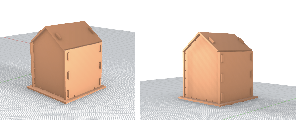
Before moving on, I tried fitting all my pieces together as a 3D modle, and all looked well.
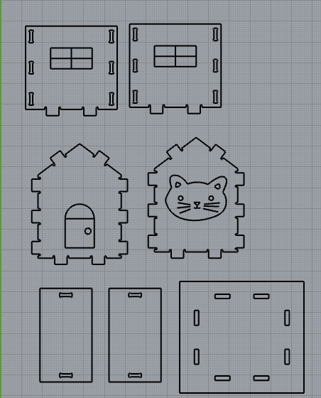
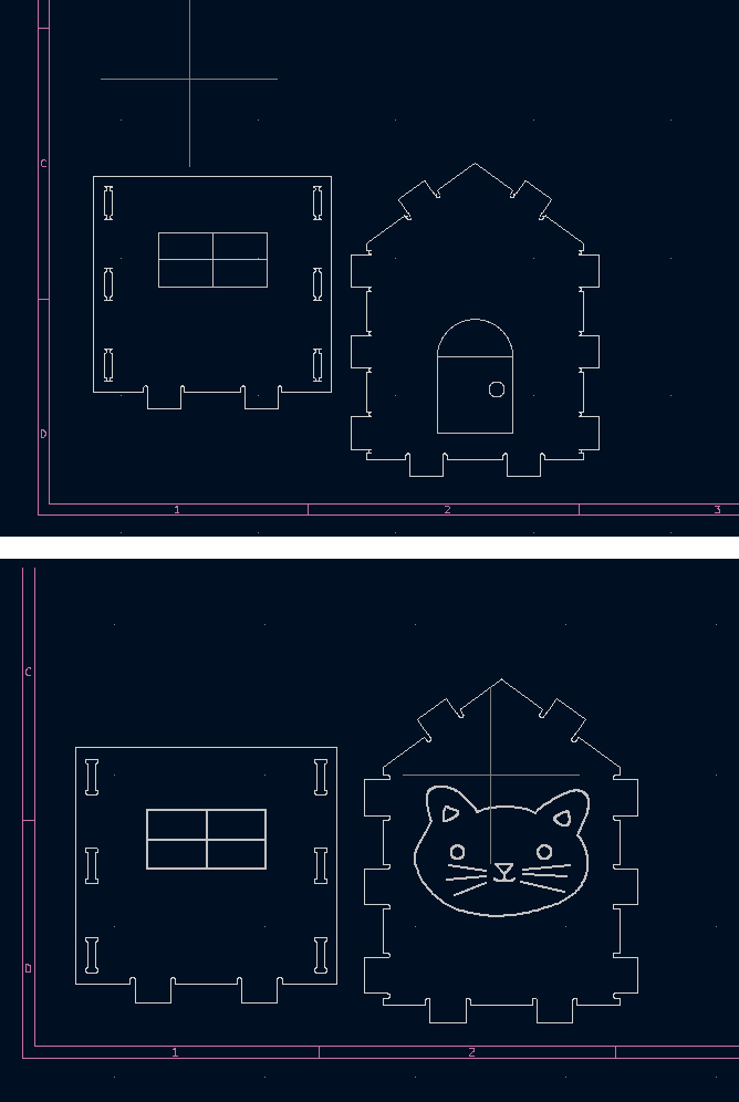
I decided to add some simple engravings of windows and a door so it looked more like a house. I also drew a cat since a couple of my friends also added animals to their projects. The cat was drawn in Illustrator, exported as an SVG, and imported into the Rhino file.
Milling (and printing):
With these files, I headed to the Mill to mill my pieces. I got the machine all set up and converted my files to DXF. Only 2 pieces at a time would fit on one piece of FR1 so, I placed one house-shaped and one side panel in my first file to cut.
I imported them into KiCad as instructed in the lecture and slides. I followed all the settings, and set my engraving thickness 0.3mm. It looked A-Ok in KiCad, so I went to set up in Bantam.
I measured both my sacrificial layer and my cutting layer and they were both 1.4mm. After installing the bit, homing, performing the touch-off, and sufficiently taping my FR1 layers (I learned from our in-class attempt at taping that you can’t just use a few pieces), I started milling. Yay!
But my happiness was short lived, as the moment the bit touched my sheet, it broke. I immediately thought something was wrong with my settings and offsets, so I double checked my settings with my classmates who were working at another machine successfully. Everything looked exactly as they had it, so I wasn’t sure what the problem was. Perhaps I installed the bit incorrectly? So, I started over.
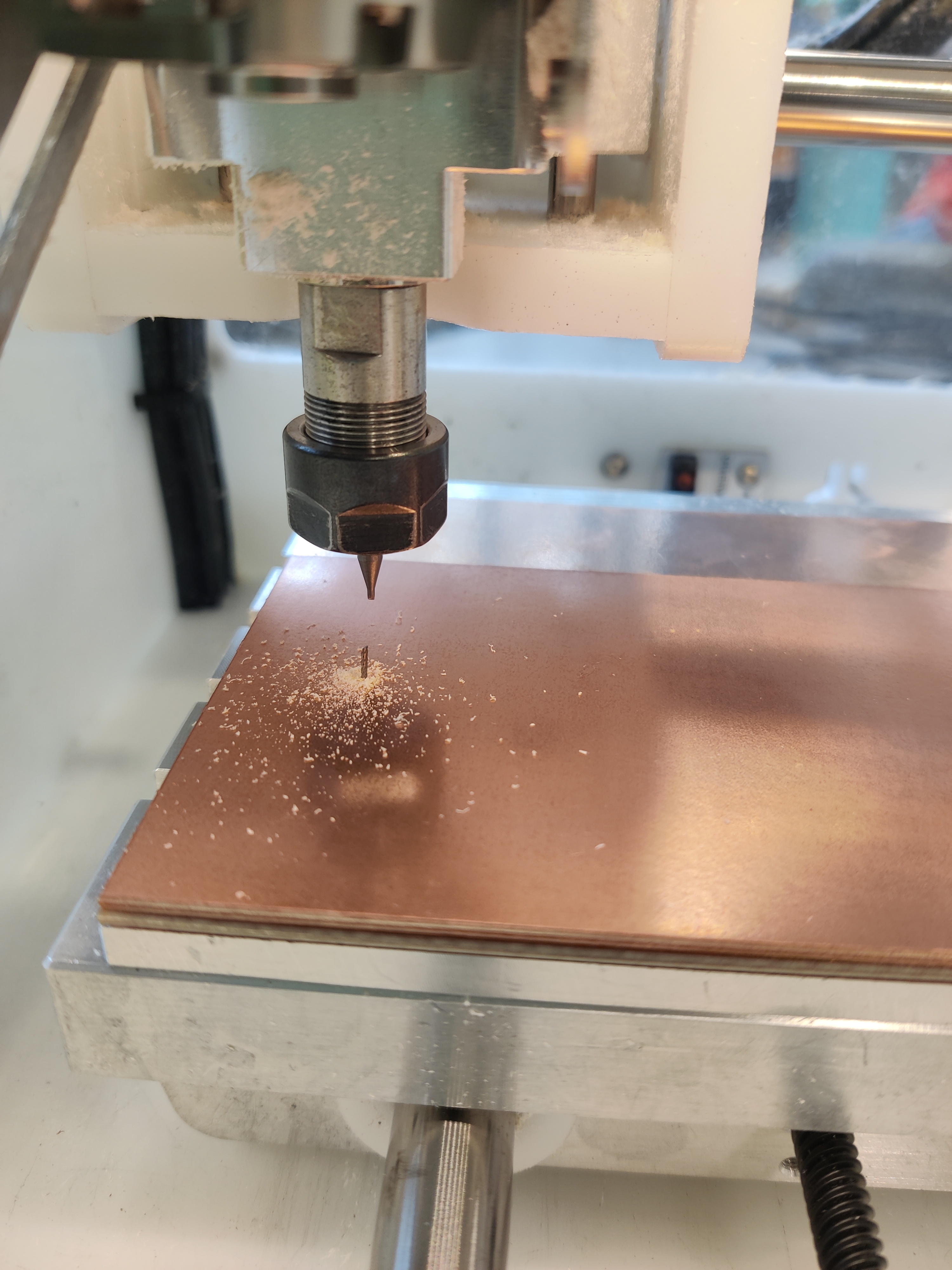 Broken bit : (
I really did not want to be responsible for breaking any more bits, so I went back to look at everything that I had. Upon further scrutinization of my files, I realized some oddities (though I don’t believe they had anything to do with what was happening with the machine)
In KiCad, it looked like a bunch of my dog bones were inverted, and in Bantam, it looked like one of my outlines had a thick double outline. After posing some of my questions in Slack, Noelle suggested exporting the DXF as “2007 lines”, which solved all these issues!
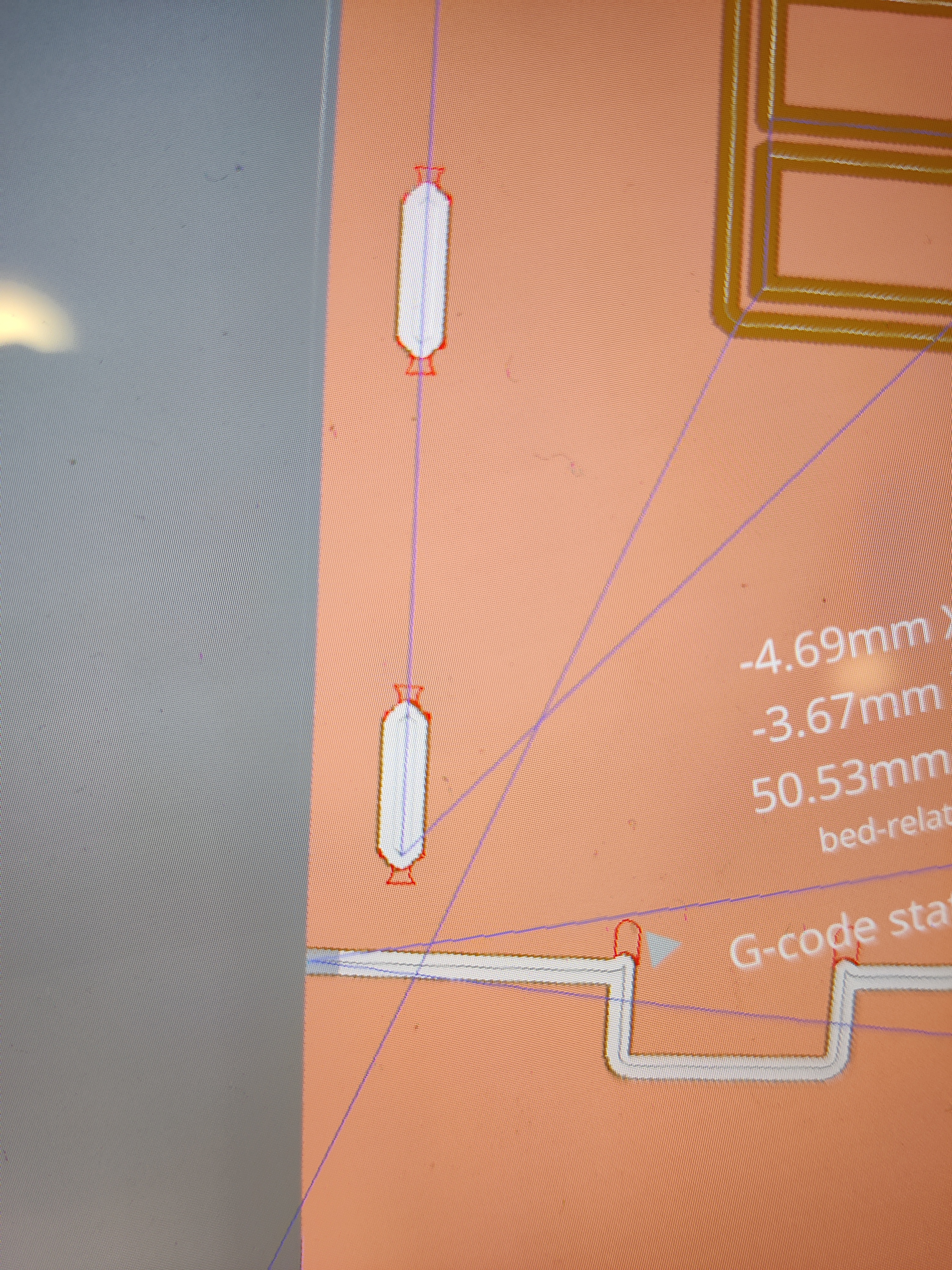 Inverted dog bones
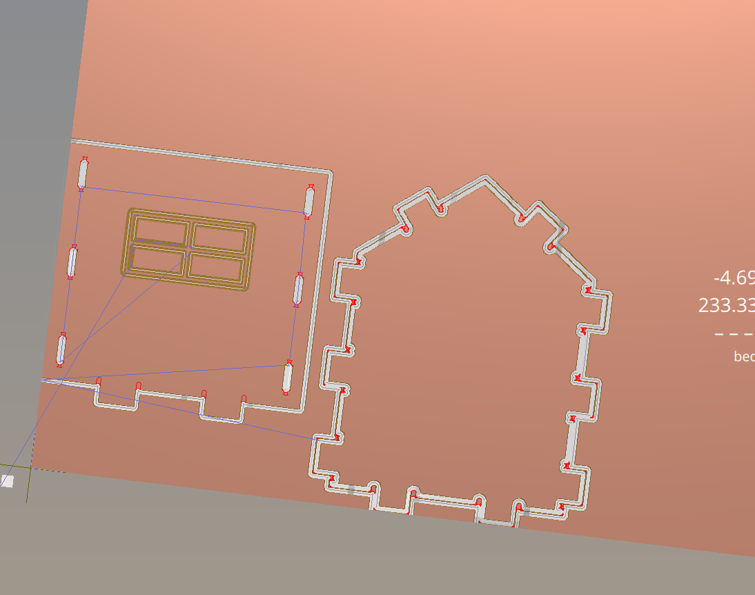 Thick double outline
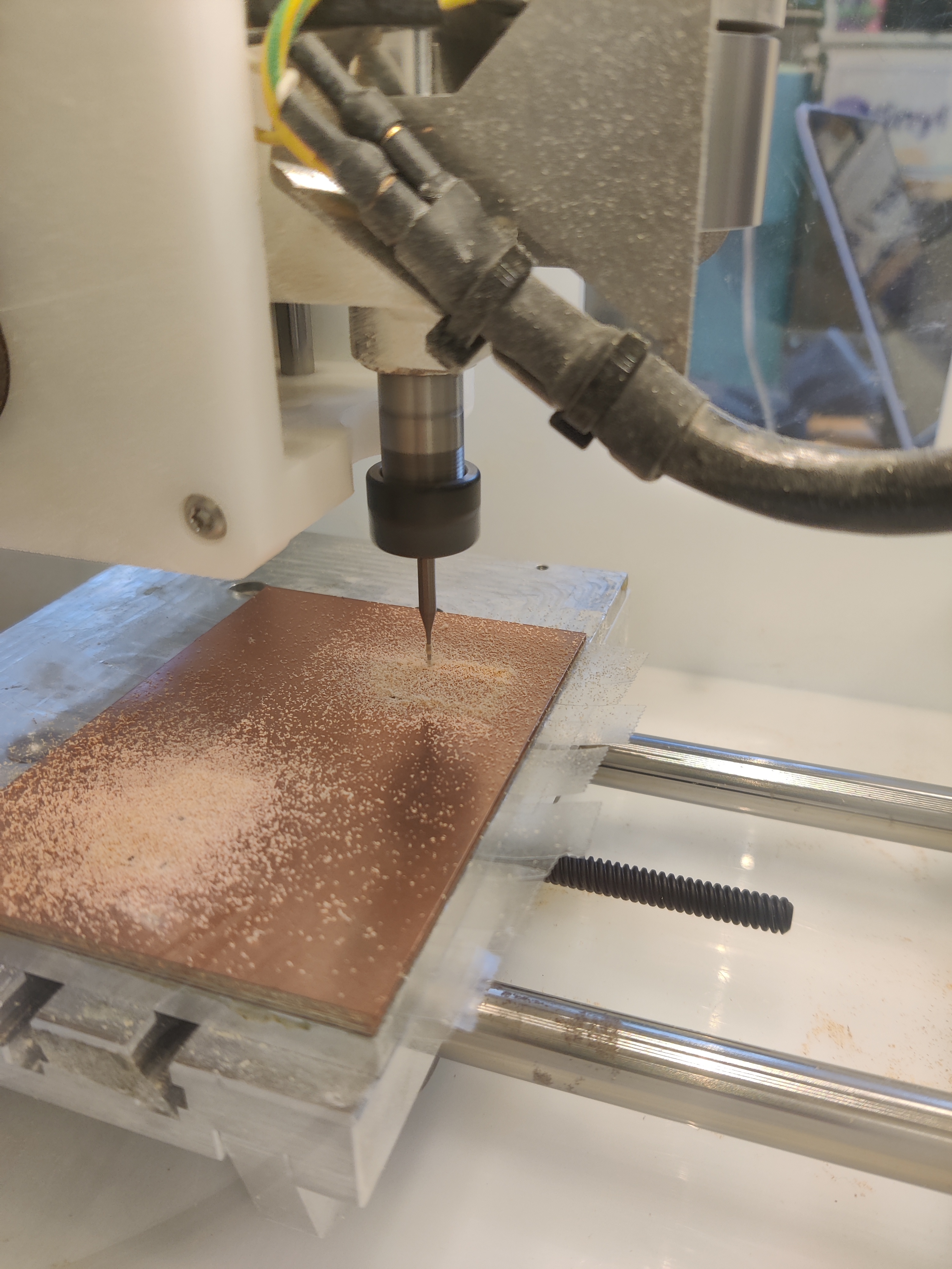
Now with all my files in order, I could try again. At this point, we decided that it might be a machine issue, so I tried on another machine that was working for others.
It cut!!!!
After chatting with Belinda, we solidified the hypothesis that it was probably a machine issue, since she had the same problem with the bit breaking, but her cuts also worked on another machine with the exact same settings.
Now, this is where I remembered that it was mentioned at one point to scale the slots or tabs to increase the chances of it fitting and accounting for any discrepancies while milling. Since my tabs and holes were the exact same size, they did not fit together. I had to file down the tabs quite a bit, making them thinner by sanding from the back and shorter by filing the sides. The paper that I was using was super old and worn, but all they had at the Mill apparently. I couldn’t really sand precisely, but got it just enough for the pieces to kind of fit, though not flush with each other, which will cause problems later on…
I was running out of time, so I decided I would try to at least cut the four side panels for the house. The second piece cut without a hitch, so I just had to sand some more. With no time to spare, I got all 4 of my pieces to fit together (again, not flush).
 In progress cutting
 Yay!
Yay!
I did not have more time to go to the Mill, so I decided to 3D print my last few pieces (2 roof pieces and base). Before printing my roof panels, I wanted to make the slots bigger so that the tabs on the roof would fit. However, I printed the wrong file, and in my rush I didn’t even realize it and thought the holes were just too small again. Before I realized, I already sanded the tabs again and fit the roof to the house.
The last thing to do was the base, which I theoretically already had a file for as well. However, since the pieces are not sitting flush with each other, the dimensions are not the same as they were in my initial plan anymore. This didn’t occur to me until I printed a base and it did not fit at all. After another failed attempt at printing base, I sat down and measured everything that would go into the base with calipers and drew out a diagram.
I crossed my fingers and printed. It just very barely fit together. But it did. It felt so good to be done!
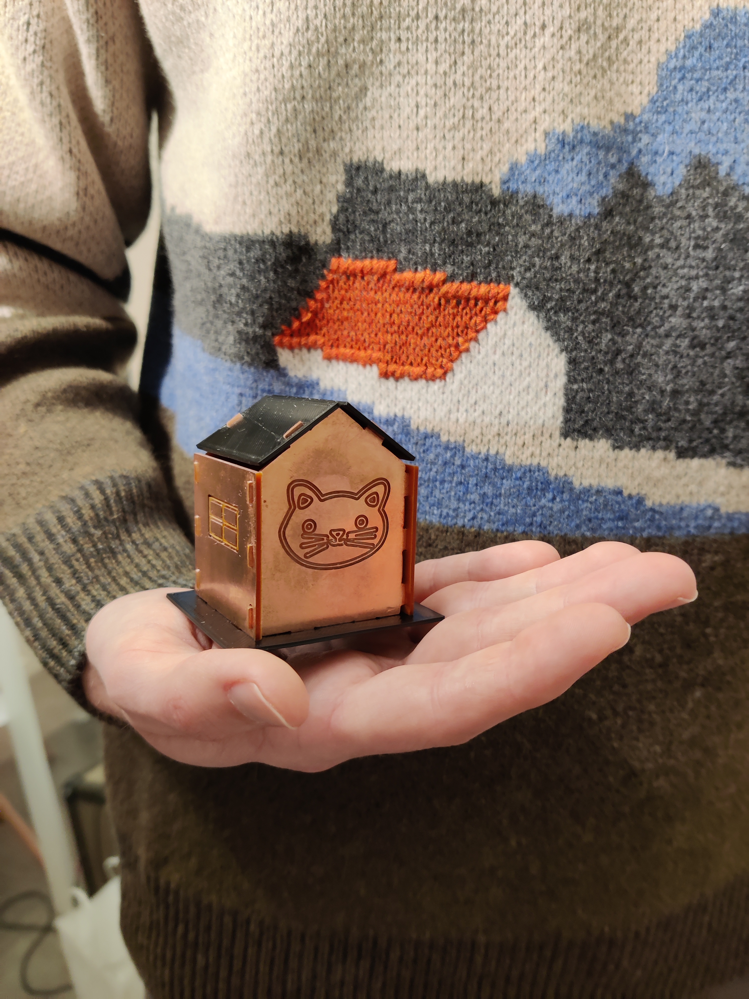
^^ My partner who thought that it was cute that it kind of matched his sweater
Credits:
- Annie, Vanessa, & Belinda for support and troubleshooting together at the Mill
- Noelle for suggesting exporting as 2007 lines
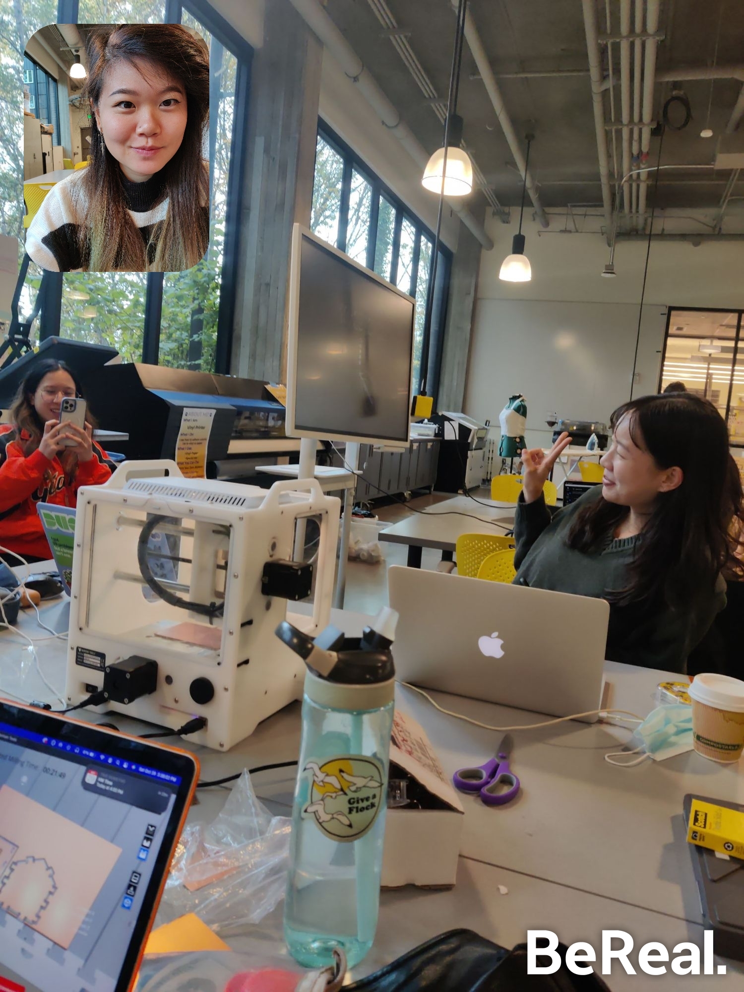 Being Real at the Mill